Extracting Window Semantic Metadata in Unity
Background
In addition to the standard UV texture map, Geopipe models contain a secondary UV map that is unique to each building facade within a model. This UV map can be used to uniquely identify a building and its features. If you want a general overview of the concepts behind this shader, check out our Window Metadata page.
Set up a ShaderGraph
These instructions use Unity’s ShaderGraph. If you are using Unity’s standard renderer, install the ShaderGraph package before following along. If you are using a different game engine or 3D renderer, use the provided graphs and code as a base for your own shader and feel free to reach out to us if you have any questions.
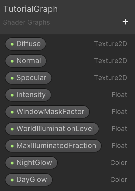
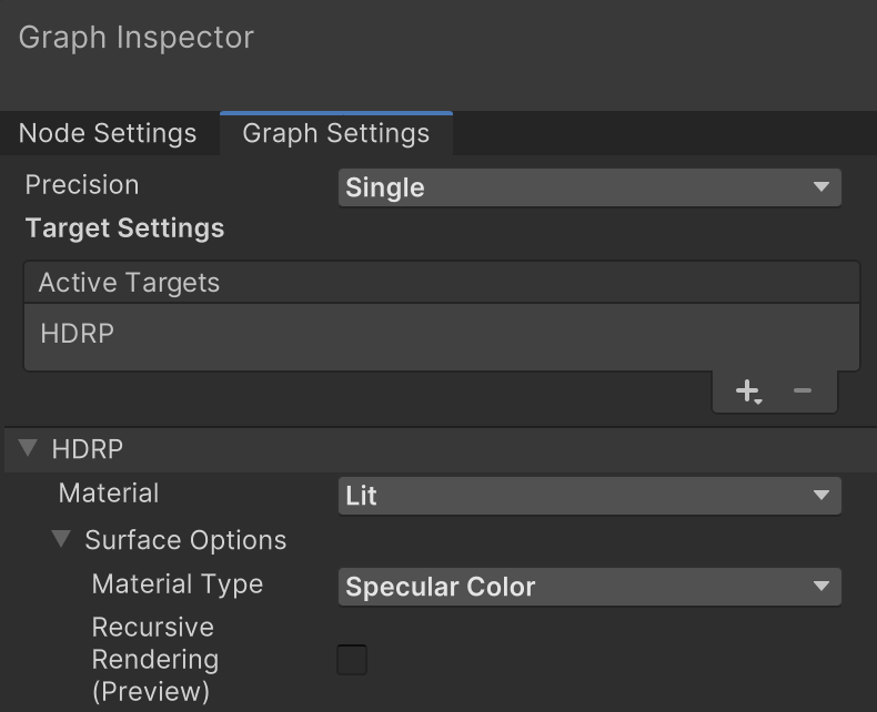
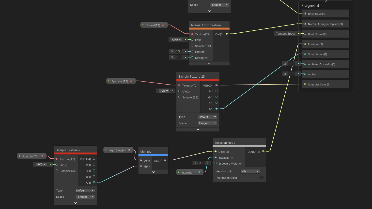
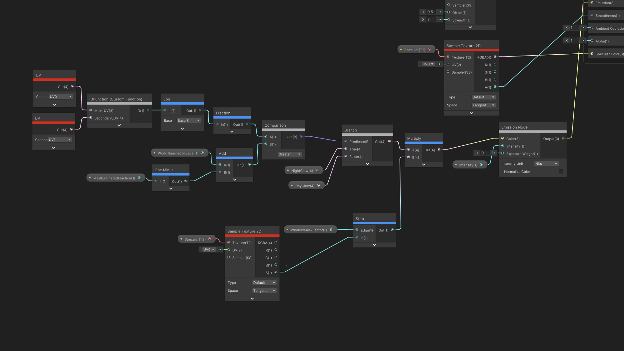
First create a new ShaderGraph. In the graph inspector’s graph settings, set the material type for your shader to specular color. Then add the following inputs using the + button on the ShaderGraph blackboard.
- Diffuse, Normal, and Specular as Texture2D inputs. These are the textures that you will see on the side of each building.
- Intensity as a float. This property only makes a difference if you are using the HDRP rendering pipeline. This will determine how bright the windows should be.
- WindowMaskFactor as a float. This value is the threshold to extract the location of a window from the specular texture.
- WorldIlluminationLevel as a float. This is an input that tells the shader how much light is in the world. When WorldIlluminationLevel equals 0.0, all the windows will be glowing. When WorldIlluminationLevel equals 1.0, none of the windows will be glowing.
- MaxIlluminatedFraction as a float. In the real world, not all of a building’s windows are glowing at night. When MaxIlluminatedFraction equals 1.0, all of a building’s windows will be glowing when WorldIlluminationLevel equals 0.0. When MaxIlluminatedFraction equals 0.8, only 80% of the windows will be glowing when WorldIlluminationLevel equals 0.0.
- NightGlow as a color. This is the color that windows will be glowing when they are turned on. This tutorial uses solid yellow (Hex #FFFF00), but you can change it to any shade that fits your needs.
- DayGlow as a color. This tutorial uses solid black, because windows do not glow during the day. If you wanted to create a stylized world, you could change this color so that windows appear different during the day.
Then, set up the provided materials to the correct outputs of your shader. The fastest way to add nodes will be to right-click in the empty space on the graph, select “Create node”, and start typing the name of the node. Then click and drag from each node’s output into the other nodes’ inputs. To add node inputs defined in your blackboard, drag them into the graph.

Saving ShaderGraphs will not happen automatically, and Ctrl/Cmd+S will not save your graph. Every time you wish to save your ShaderGraph, you must manually press “Save Asset”.
Import your model
Follow the instructions from https://docs.geopipe.ai/models.html. You can skip the instructions that describe how to set up the windowed materials because this shader will replace those materials.
Add the Shader to Your Building
In the folder where you extracted your materials, find one of the materials that corresponds to a windowed material. Make sure to note the name of the default texture. It should use the following naming scheme:
windowedFacade_{material}_{number}_diffuse_1024.png.
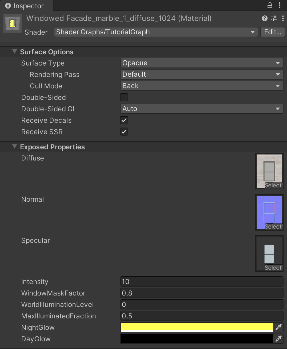
The inspector window should show that the material currently uses a “Standard”, “HDRP/Lit”, or “Universal Render Pipeline/Lit” shader. Select that dropdown menu, go to the Shader Graphs section, and select your shader. Then set the following properties on your material.
The Diffuse property should receive the material’s default texture that you found previously.
The Normal and Specular properties should receive the textures that have similar names to your diffuse texture, but end their names with normal and specularGlossiness respectively.
Certain file formats will not contain Normal textures. If you are using such a model, you can ignore the normal map for the purposes of this tutorial.
Finally, set the NightGlow property to a yellow color, Intensity to 5.0, and WindowMaskFactor to 0.8.
You will want to repeat this process for all the windowed materials.
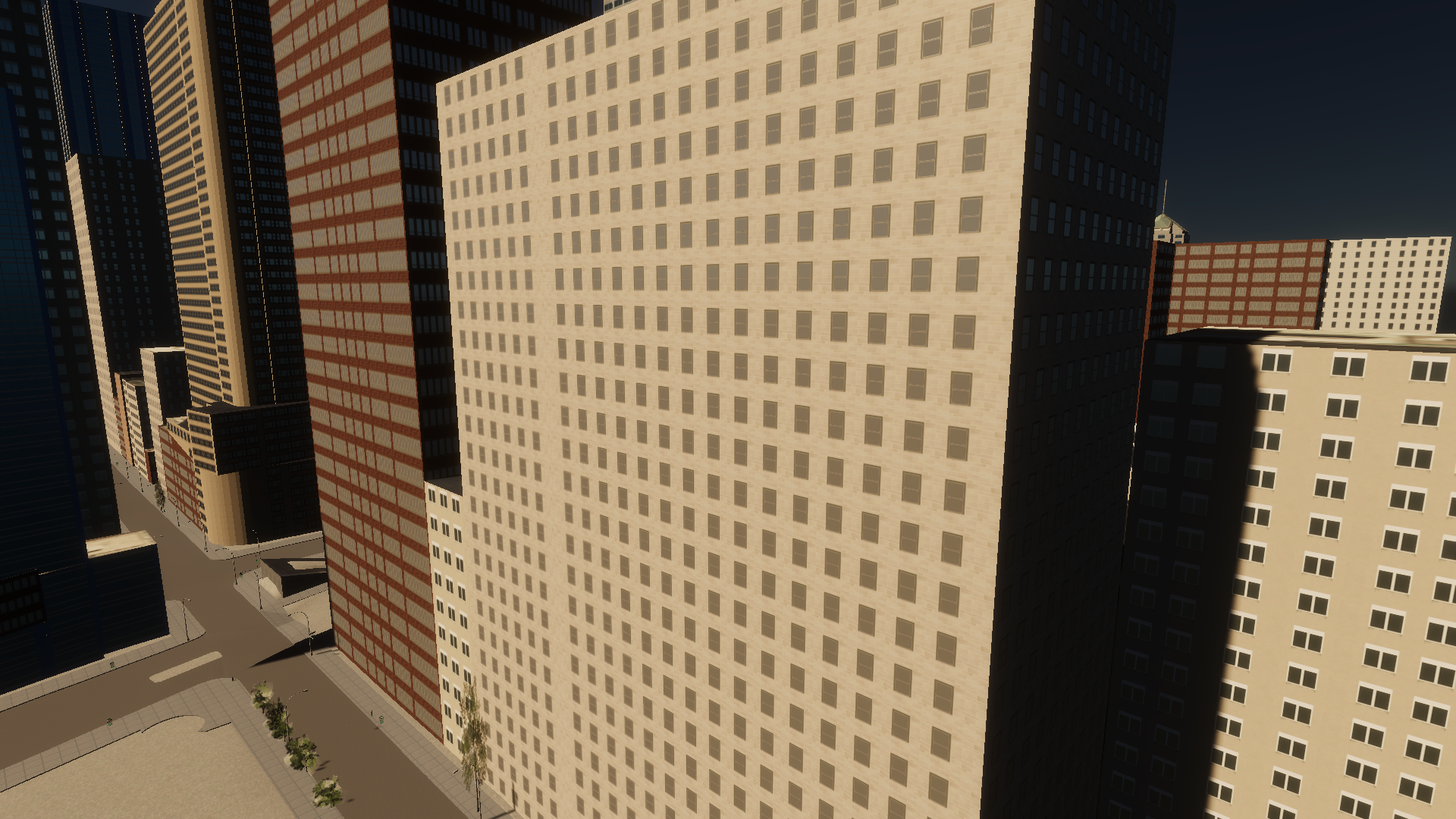
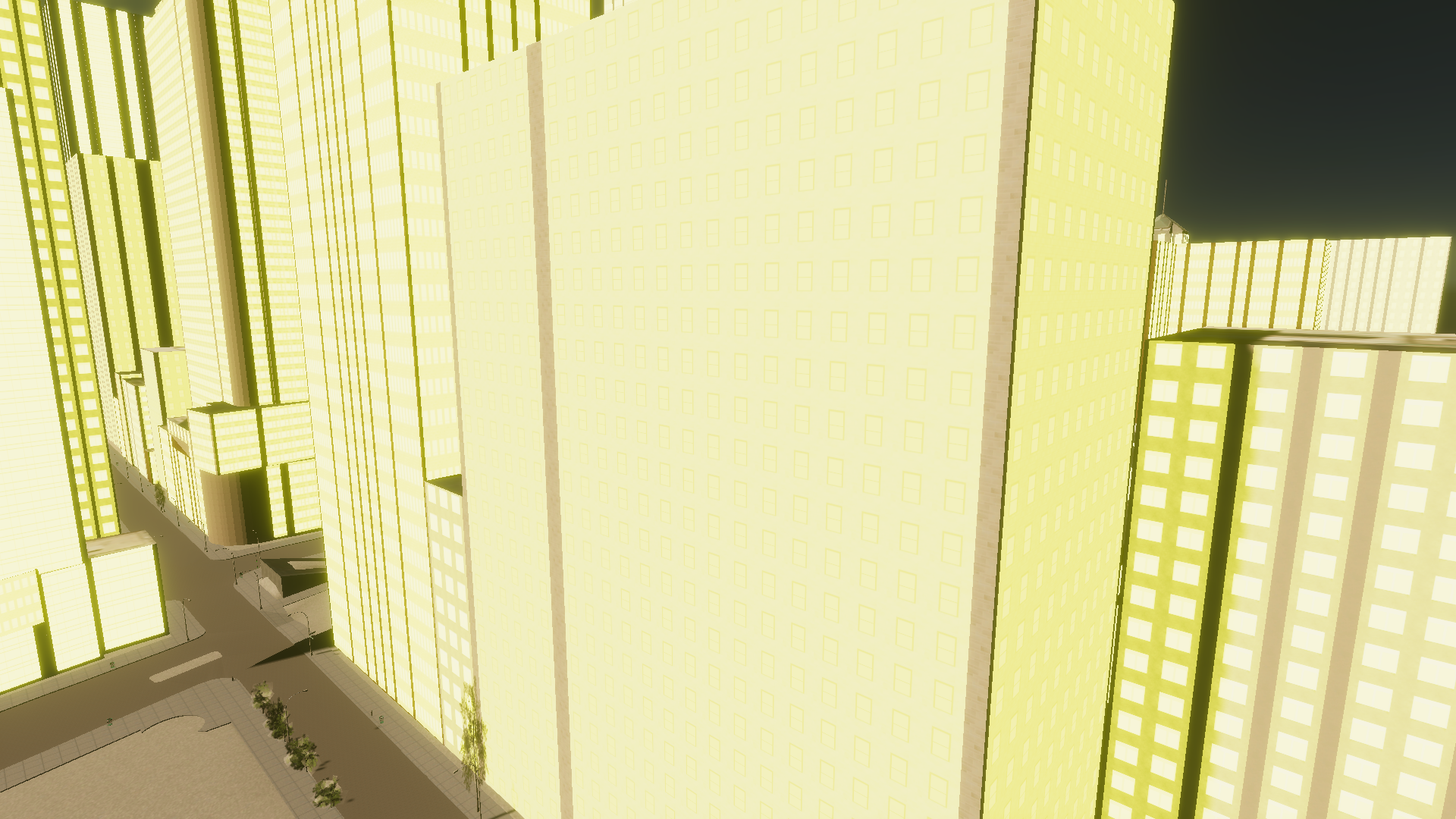
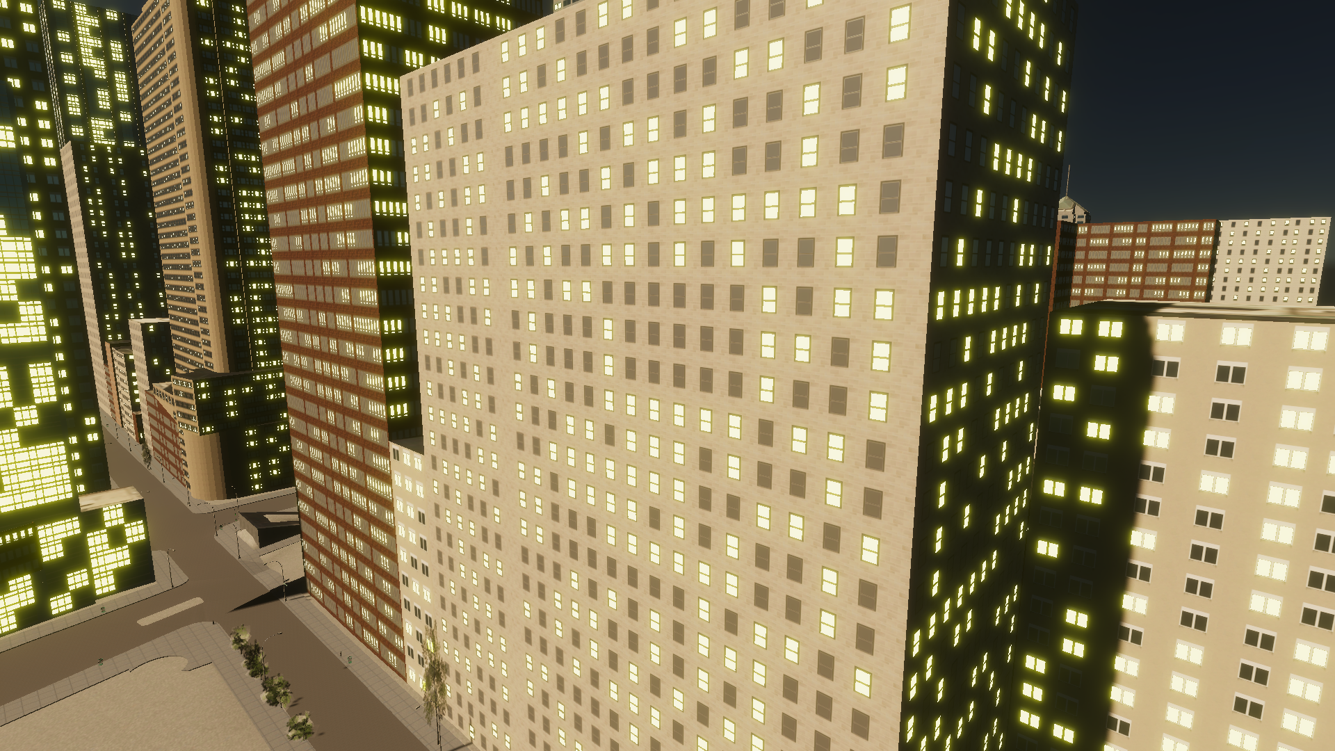
The following image shows the shader applied to the windowed materials that make up this building.
Identify the Location of Each Window
In order to light up windows, we first have to extract a window mask from a texture. A good candidate for this role is the alpha channel from the Specular texture. Multiplying the alpha channel of the Specular texture by NightGlow will only emit light from where there is specularity. Note: If you are not using HDRP, the emission node does not exist and you can directly connect the output from the multiplication node to the emission input.
Hm, that doesn’t appear correct. It appears that some of the non-window part of the specular texture contains a small amount of specularity. To remedy this, we can add a step node to only create a mask where the alpha of the specular material is above a certain threshold (WindowMaskFactor). This shader uses 0.8 as the mask factor, but feel free to change it to fit your needs. Lower numbers will make more of the area around the window glow, and larger numbers will make less of the window glow.
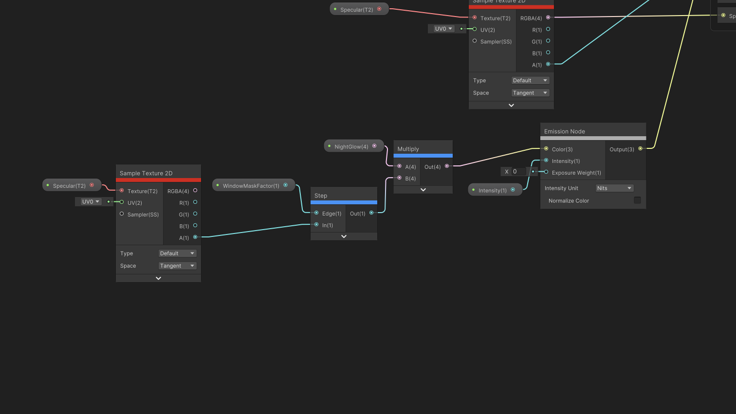
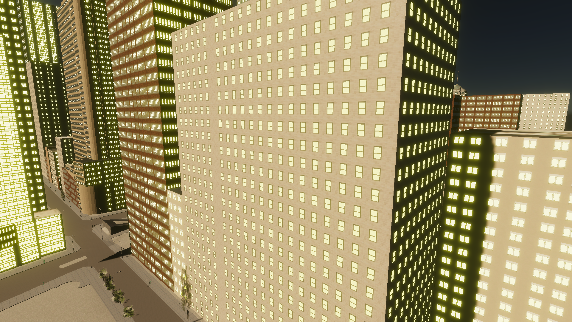
Much better.
Extract an ID from Each Window
Although glowing windows look nice, we want to extract the window IDs so that each window can look different. To accomplish this task, we will use a custom shader that takes in the main UV and secondary UV as input and outputs an ID for each window.
Within your project, create a file named IDShader.hlsl and paste the following code into it.
#define FLOAT_MANTISSA_BITS 23
#define FLOAT_MANTISSA_MASK ((1 << FLOAT_MANTISSA_BITS) - 1)
void IDFunction_float(float4 uv0, float4 uv2, out uint id) {
   // This extracts the number of rows and columns in the facade
   float rows = floor(uv2.y);
   float cols = floor(uv2.x);

   // This extracts the row and column position of the current window
   uint row = (uint)floor(uv0.y * (rows + !rows));
   uint col = (uint)floor(uv0.x * (cols + !cols));

   // This extracts the unique facade ID by concatenating the fractional
   // portion of the UV2 map
   id = (asuint(uv2.y) & FLOAT_MANTISSA_MASK) ^
           ((asuint(uv2.x) & FLOAT_MANTISSA_MASK) << (32 - FLOAT_MANTISSA_BITS))
           ^ 0x5e1a743c;
   // This incorporates the row and column of the window with the facade ID
   // to produce a sufficiently random window ID
   id = (id << (col + 1 + (uint)sqrt(row))) ^ (id >> (row + 1)) ^ id;
   id = (id << (row + 1 + (uint)sqrt(col))) ^ (id >> (col + 1)) ^ id;
}

void IDtoColor_float(uint id, out float4 color) {
    color.r = (float)(id >> 22) / (float)((1 << 10) - 1);
    color.g = (float)((0x0fff) & (id >> 10)) / (float)((1 << 12) - 1);
    color.b = (float)(id & 0x03ff) / (float)((1 << 10) - 1);
    color.a = 1.0;
}
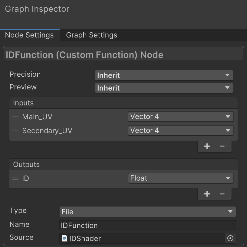
Within the ShaderGraph, create a custom function node. Give it two float4 inputs named Main_UV and Secondary_UV and a float output named ID. Set the name to IDFunction and add the IDShader.hlsl file as the source.
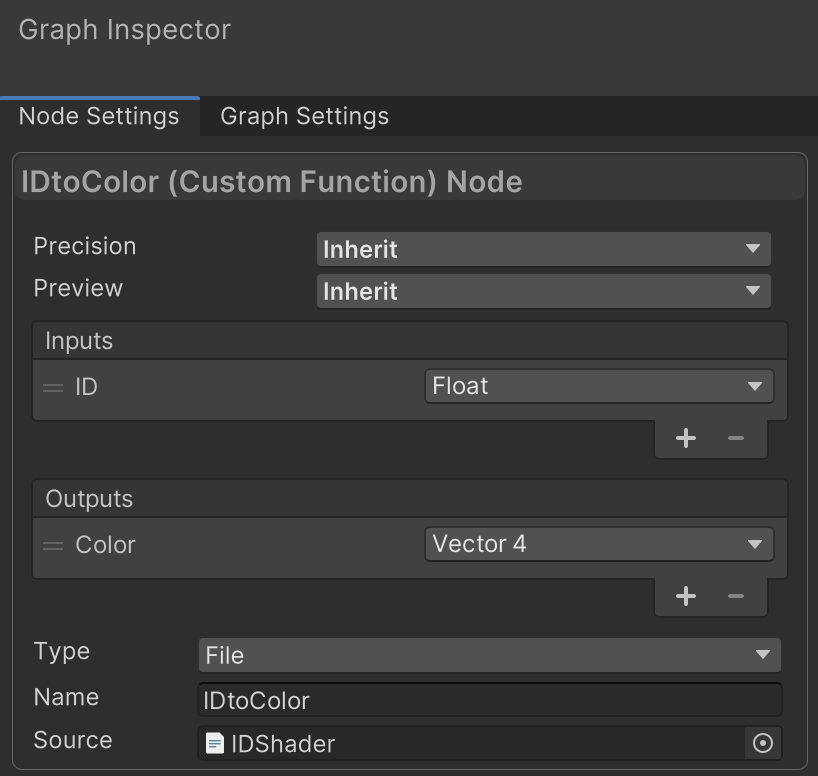
Before we turn this ID into an on/off switch, let’s visually confirm that the windows have different IDs. This can be done with another custom function node that takes an ID float as input and produces a Color vector4 as output. Set the function name to IDtoColor and use the same IDShader.hlsl file as the source. This custom function extracts an RGB color from the bits that make up ID.
Connect two UV Geometry inputs to our IDFunction node, which has its ID output in turn connected to the IDtoColor function. Confirm that the UV0 channel is connected to Main_UV and the UV1 channel is connected to Secondary_UV. For now, replace NightGlow with the output Color from the IDtoColor node.
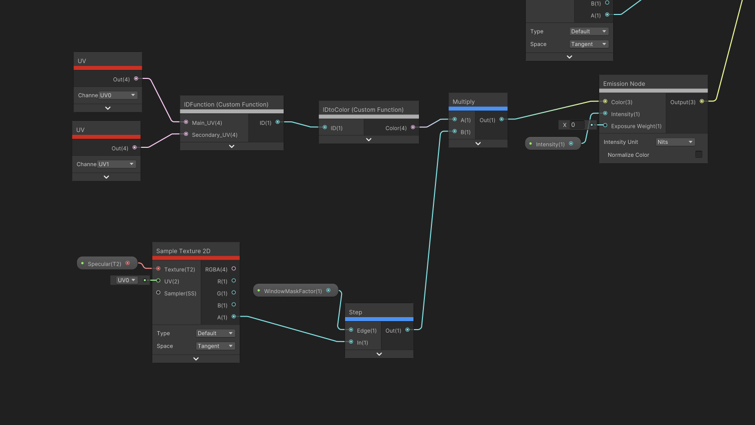
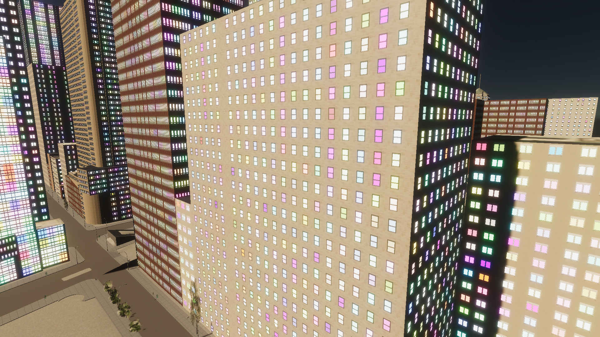
Disco time!
Use the Window ID to Control the Light State
Although the disco windows look nice, we still do not have any control over whether or not a given window is lit.
The function WorldIlluminationLevel + (1 - MaxIlluminatedFraction) produces a threshold that determines if a window should be lit or not. As WorldIlluminationLevel decreases, the threshold also decreases, and more windows are lit. As MaxIlluminatedFraction decreases, the threshold increases and fewer windows will be lit.
To compare the window ID to that threshold, we want a function that maps the ID to a value between one and zero. If the mapped value is greater than the threshold, then the window should glow. This shader uses the fractional part of the natural logarithm of an ID as that function. Although not a perfect choice for all IDs, it is sufficiently useful for this tutorial.
Once we’ve compared the state of the mapped ID to the threshold, we need to tell the shader to light up the window in a certain way. A branch node is used so that if the comparison was true, then the window emits its NightGlow.
This shows the facade with WorldIlluminationLevel = 0.0 and MaxIlluminatedFraction = 0.5
Next Steps
And that’s it! Now you can play around with the different settings to customize the window shader to your liking, or you can take the facade ID and apply it to different tasks.
Use the following bullet points as inspiration for your future projects
- The lights currently just turn on and off. Adjust the shader so the windows slowly turn on and off
- Create a script that converts the position of the sun into an illumination level so that the windows automatically turn on at night time and turn off at sunrise.
- Instead of turning on/off all the windows at roughly the same time, some rooms get re-used during the night as people use them for different meetings. Rework the shader so that windows can turn on and off throughout the night.